How to Draw Axonometric Projections: A Step-by-Step Guide to Mastering 3D Visualization
How to Draw Axonometric Projections: A Step-by-Step Guide to Mastering 3D Visualization
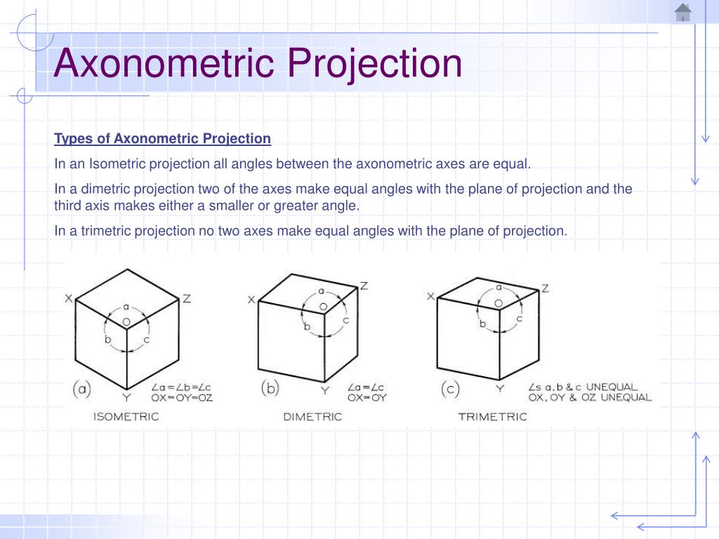
Mastering axonometric projections unlocks a powerful tool for architects, designers, and engineers seeking precise, intrinsically accurate 3D representations without the distortion of perspective. Unlike simple isometric or dimetric views, axonometric drawing preserves dimensional integrity across all three axes—x, y, and z—allowing viewers to perceive true spatial relationships. This guide reveals a methodical approach to creating axonometric projections, transforming complex geometric relationships into clear, visually reliable images that support design clarity and technical communication.
The process begins with understanding the fundamental principles that distinguish axonometric techniques from other projection systems. Axonometric projections maintain consistent scale along each axis, meaning one unit forward in the x-axis equals the same distance as one unit forward in the y or z. This consistency enables accurate size representation, making axonometric drawings indispensable in technical documentation and conceptual design.
“Axonometric drawing reveals the whole picture without hiding it,” notes architectural visualization expert Maria Chen, emphasizing that proper execution removes visual ambiguity and supports precise spatial judgment. To lay a solid foundation, proper preparation is essential. Start by commissioning a clean, isometric grid—typically a rectangular planar base where axis lines align cleanly.
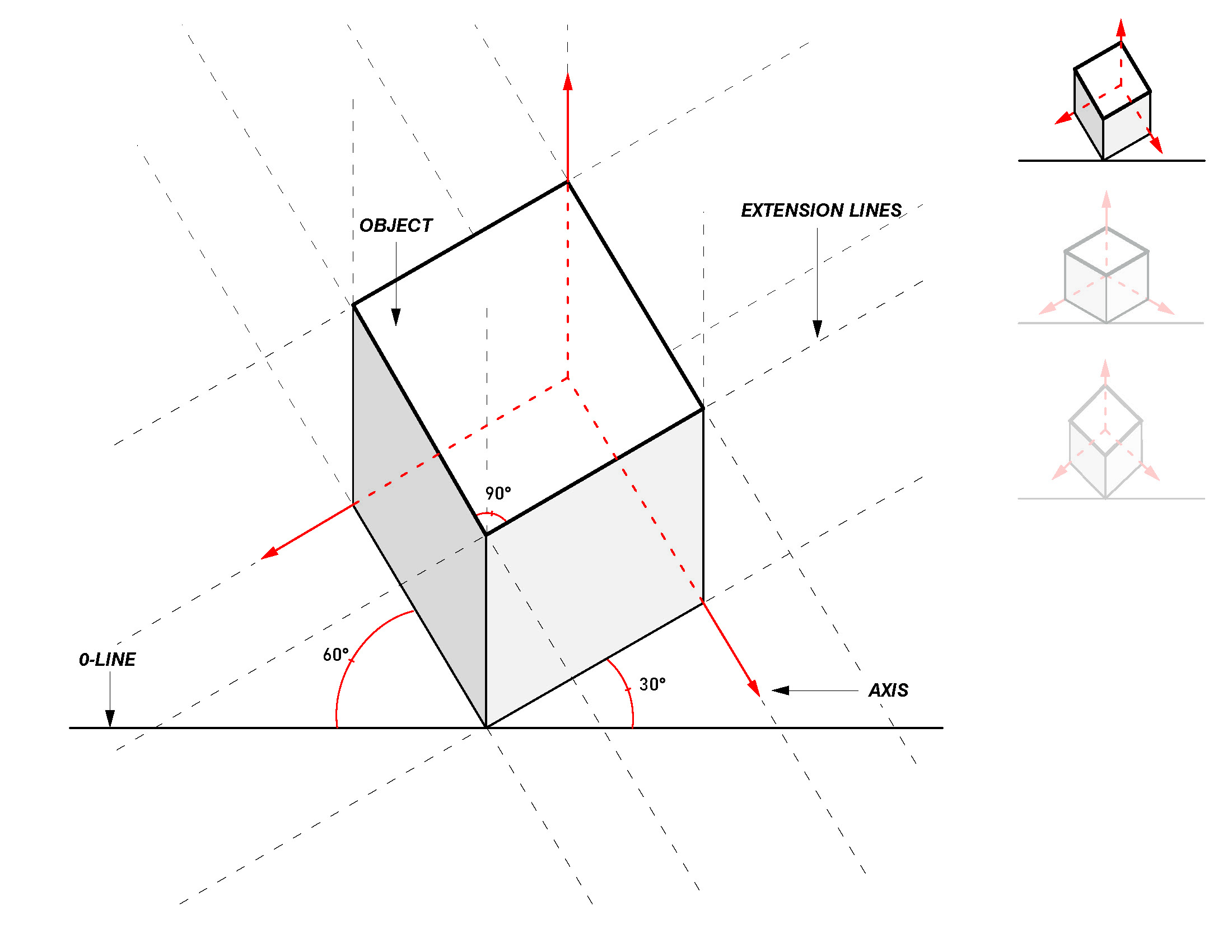
Most designers begin with a rectangular floor plan drawn at 30- to 45-degree angles: the horizontal and vertical axes diverge at 90 degrees from the front view, but remain parallel to each other, unlike isometric, where they diverge symmetrically. This deviation from strict 30-degree angles preserves parallelism on the page while advancing depth accurately. “The foundation is unsung but critical,” explains visualization artist Raj Patel, “a well-structured grid ensures every dimension flows logically from point to point.” Once the grid is in place, the next step is defining the three core axes—typically labeled front, right, and depth.
In axonometric projection, these axes are not symmetrically rotated as in isometric; instead, the depth axis (often vertical) advances uniformly away from the viewer, while the horizontal axes retain consistent horizontal scaling. The front axe (x) moves forward, the right axe (y) extends rightward, and the depth (z) recedes or advances along a receding diagonal—usually measured at a standard scale of 2:1 or 3:1, meaning each unit of depth equals two or three units horizontally. This deliberate scaling maintains relative size and aligns components spatially without distortion.
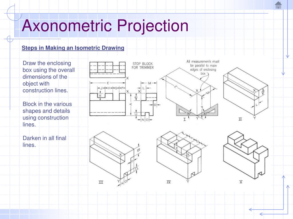
- Plot the Front and Right Axes: Begin by establishing perpendicular axis lines from a central origin. The front axis runs straight forward; the right axis extends rightward. Their intersection forms the base of the projection volume.
Use a ruler or straightedge to ensure crisp, accurate angles—even minor deviations compromise dimensional fidelity.
- Define Depth Progressively: Along the depth axis, mark discrete progressions—commonly four to six uniform steps representing scale increments. Each step should advance at the same proportional rate (e.g., 1.5 cm per unit) to maintain visual consistency. This stepwise approach enables careful vertical placement of objects without confusing perspective cues.
- Position Objects Using Vector Logic: Once the grid and axes are firm, apply geometric rules to place elements.
For walls, furniture, or structural members, anchor their lines to the grid, respecting axis alignment. Vertical elements converge back to a vanishing point along the depth axis, rendered parallel to preserve proportionality—this careful convergence avoids the use of foreshortening found in forced perspective.
- Apply Correct Scaling and Aspect Ratio: Unlike isometric drawers that compress depth for visual symmetry, axonometric projections preserve true scale along each axis. Scale reduces uniformly with distance; a wall 1 meter wide in front remains 1 meter wide at depth—but this width diminishes proportionally as z increases, measured precisely against the established grid.
Maintain 1:1:1 or 2:1 depth-to-width ratios for consistent interpretability.
- Clarify Layering and Elements: To avoid visual noise, group components by functional zones. Use subtle line weights—thicker for primary structure, thinner for non-load-bearing elements—while maintaining consistent depth representation. Transparency or grid overlays can aid clarity, especially in complex assemblies, but must remain unobtrusive to preserve projection integrity.
- Verify Dimensional Accuracy: After completing the layout, conduct a dimensional audit: measure known distances along each axis and confirm they reflect true scale.
Did the wall span two units horizontally and three depth units? Confirm proportional harmony across all axes.
- Finalize with Annotations and Legends: Label critical dimensions, axes, and project titles clearly. Include a scale bar anchored to the grid—ideally 1:50 or 1:100—to ground the viewer’s spatial sense.
A small legend distinguishing horizontal, vertical, and depth lines enhances interpretability for technical audiences.
This is not merely artistic skill, but a disciplined approach to technical visualization that empowers clearer decision-making and stronger communication across disciplines. In an era where digital tools often obscure geometric rigor, mastering axonometric projection serves as a bridge between abstract concept and tangible understanding. Whether designing a skyscraper footprint or mapping industrial layouts, the clarity gained through this method ensures that every line tells an honest spatial story.
The process, though methodical, rewards patience and attention to scale—proving that even complex three-dimensional space can be rendered with clarity, one axis at a time.

Related Post
Mike Haddad WMUR Bio Wiki Age Height Wife Salary and Net Worth

Enzo Zidane: The Quiet Architect Behind a Dynasty of Football Genius

Exactly 5 Ft 8 In Cm: The Global Standard Shaping Space, Safety, and Design
Spoiler WWE RAW Superstar to Challenge Lyra Valkyria for the NXT Womens Championship